I start micro controllers with new projects / experiments to some ideas / module / shield is seen after some time ago, my old project “2.4 Inch TFT LCD Control By Arduino Atmega " that would fit in perfectly found something interesting.
If you are interested in it, then link on my profile can search. I do not want to insist too much on this. It's a project I'm working on at the time and says undergone many transformations. I will not ever finish it, but I think working on / posted here will be some of whom have learned many interesting things discovered.

I'm excited with the idea of the visual feedback the XY controller (PAD) to make the TFT touch screen display was to use.
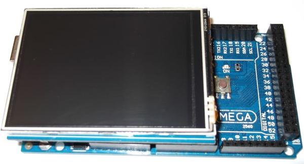
Shield’s Overview:
- Resolution: 240x320.
- Size: 2.8 Inch.
- Colours: 262K
- TFT driver: ILI9325DS (supported by UTFT library)
- Touch driver: XPT2046

Interface:
- TFT: 8bit data and 4bit control.
- Touch Screen: 5 bit.
- SD: 4bit.
TFT Hardware Setup:
Installation is straightforward. You still need to select the correct voltage before use is. SD socket next to it, is a switch in the top right. 5V for Arduino Uno Arduino Mega and must choose. It is also not completely push shield.
Library Setup:


- First you need to install UTFT library. I'm going to do. You never know what might happen in the future.
- Same thing about UTouch library.
Touch Screen Calibration:
To work properly, the touch screen calibration is needed. UTouch revised calibrations to the library we need to run this sketch. We UTouch UTFT library with the library needs to match the orientation.

myGLCD.InitLCD(LANDSCAPE);
myTouch.InitTouch(LANDSCAPE);
These are 4 phases. In which we need to edit line #define selector for every phase and upload and run sketch step by step:
#define selector 1
In this phase we will verify that simple calibration put the correct resolution. This is an optional step. I put it here because the solution was designed by the author.
#define selector 2
It is the most important of the four. Here is the calibration. After uploading you like to sketch the picture top left point and the right - to get to the point; and amend.
void UTouch::InitTouch(byte orientation)
{
orient = orientation;
_default_orientation = 0;
touch_x_left = 306; //enter number for left most touch
touch_x_right = 3966; //enter number for right most touch
touch_y_bottom = 3906; //enter number for bottom most touch
touch_y_top = 174; //enter number for top most touch
disp_x_size = 320; // do not forget them if different
disp_y_size = 240; // do not forget them if different
prec = 10;
// ..................................................
We have to get to the screen touch_y_bottom values and values in relation to touch_y_top swapped looking. (TFT touch screens the origins of axes are different from the original). You will find out that the TFT for each model. You y -axis or x- axis values of the TFT model dependent or may not need to swap. This particular model of the above works.
#define selector 3
Test program. Display XY coordinates of the touch point.
#define selector 4
Test program. Put a white pixel on the touch point. It is still very comfortable. If you see that you need to swap axis values for x or y axis is mirrored on those pixels.
Example:
Everything is fine with calibration, so we have to move forward and UTFT and UTouch libraries can run the examples.
This is a direct reflection shoot camera appear usable pictures of the TFT was quite difficult to take note. I tried to photograph a mirror surface, so it seems like.


XY MIDI Pad:
You've seen the last instance they run quite slowly run. There is nothing wrong with TFT display and it is nothing wrong with the code or libraries. We 16MHz (or 20MHz) try to use an 8-bit microcontroller is it? We can send data than can run very fast indeed the performance.
Indeed we can improve the code and libraries, but the changes will not be dramatic. Ideally we etc. The more powerful processor, 32- bit (even 16- bit), DMA controller, > 150 MHz, (for the video buffer) and need more RAM...
Instead we need to speed up only a small area of the screen to update our programs can design.
I here XY Pad MIDI Arduino project put the whole code. I applied what I said above can be studied in detail to see how. However, I will comment on some sections.
Festival draw_Pad (long x, long y) in, before drawing new line, old lines clear them with the background color redrawing.
 void draw_Pad(long x, long y)<br>{
// we draw 3 three lines for x and three lines for y
// for better visibility
myGLCD.setColor(pad_bk);
myGLCD.drawLine(old_x-1,pad_topY,old_x-1,pad_bottomY); // clear old line x-1
myGLCD.drawLine(old_x+1,pad_topY,old_x+1,pad_bottomY); // clear old line x+1
myGLCD.drawLine(old_x,pad_topY,old_x,pad_bottomY); // clear old line x
myGLCD.drawLine(pad_topX,old_y-1,pad_bottomY,old_y-1); // clear old line y-1
myGLCD.drawLine(pad_topX,old_y+1,pad_bottomY,old_y+1); // clear old line y+1
myGLCD.drawLine(pad_topX,old_y,pad_bottomY,old_y); // clear old line y
myGLCD.setColor(reticle_color);
myGLCD.drawLine(x-1,pad_topY,x-1,pad_bottomY); // draw new line x-1
myGLCD.drawLine(x+1,pad_topY,x+1,pad_bottomY); // draw new line x+1
myGLCD.drawLine(x,pad_topY,x,pad_bottomY); // draw new line x
myGLCD.drawLine(pad_topX,y-1,pad_bottomX,y-1); // draw new line1 y-1
myGLCD.drawLine(pad_topX,y+1,pad_bottomX,y+1); // draw new line2 y+1
myGLCD.drawLine(pad_topX,y,pad_bottomX,y); // draw new line3 y
}
I have not used the well known Arduino MIDI library (like my previous
project). Instead I use a simple function to send
MIDI CC commands:
void SendMIDIControl(byte channel, byte controller, byte value) {byte tmpChannel = (channel & 0b00001111)-1; //0= channel1...1=channel2... etc
tmpChannel = 0b10110000 + tmpChannel; //midi data first bit allways 1,
//+ 011 control change command
//+ midi channel
byte tmpController = controller & 0b01111111; //midi data first bit allways 0
byte tmpValue = value & 0b01111111; //midi data first bit allways 0
Serial1.write(tmpChannel);
Serial1.write(tmpController);
Serial1.write(tmpValue);
}
Important.!
We can not use the first serial port pins because its pins already used by TFT Shield.
- For Arduino UNO, we must use Software Serial.
- For Arduino MEGA, we can use Software Serial or Serial1/ Serial2.
My Arduino USB MIDI Interface module can be replaced (theoretical) with a combination of MIDI Shield and USB to MIDI converter. I have not tested this way.
Final Result:
I played for a while with this project after I noticed that there is room for improvement.
 We have some physical push button with the right button can manage the settings. The pad will increase the utility. This project is a starting point for your MIDI projects (proof of concept) was designed to be as follows.
Y to X, in this case we need to make a separate map coordinates.
byte CoordToMIDI(unsigned int coord)
{
float temp;
temp=coord;
temp=temp/1.72;
return (byte)temp;
}
will change in
byte CoordXToMIDI(unsigned int coord){
float temp;
temp=coord;
temp=temp/another_value1; // depend of your virtual pad x size
return (byte)temp;
}
byte CoordYToMIDI(unsigned int coord){
float temp;
temp=coord;
temp=temp/another_value2; // depend of your virtual pad y size
return (byte)temp;
}
We can also try to use the Arduino. Using this board 3V, because my interface need 3V level converter and switch TFT situation has moved on.
Huge thank to pay attention for this post.
No comments:
Post a Comment