For this project, first of all, I bought the Arduino UNO from www.robomart.com. Only a few days ago , and I am completely new to this , and was bored , so I think I would try a programming my hand and wanted a set of traffic lights. So I wrote this blog.
So making the hardware necessary for this is very easy. Follow the following points:
Take your bread board
Put the red LED on the far left with Cathode in the negative rail of the board
Skip 3 rows
Put Yellow led in with cathode in negative rail
Skip 3 rows
Put green led in with cathode in negative rail
Skip 3 rows
Put the other green in with cathode in negative rail
Skip 3 rows
Put the final yellow led in with cathode in negative rail
Assembling:
Now, connect the jumpers.
Put one from each of the resistors and one from the negative rail to the Arduino UNO.
Negative rail = GND pin on Arduino UNO
Red LED = pin 12
1st yellow LED = pin 10
1st green LED = pin 8
2nd green LED = pin 6
2nd yellow LED = pin 5
Once, it’s done. It should look like this.
Final Results:
Now, for the programming (how can we programmed an Arduino), see my old posts. These will be definitely helping you. If any you have faced any problem at the time of coding, please post your question here. All done and it should be working, just upload it to your Arduino, and your set!
Feel free to post your suggestions, bugs & comment here.
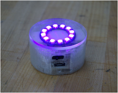
I light the facility with a bed side of the glass as the project started. I have moved forward when I explored different uses in different contexts.
The glass case of bed:
Users need to wake up and drink water, he / she turns the glass. On glass flips, it is positioned at the bottom of the glass to the light thanks to the accelerometer. After lighting LEDs, in the glass in the dark from a pitcher to pour water becomes easier for the user. The glass is turned upside down when it is closed. In this case also protects the glass from dust and dirt.
For this scenario, a coloured light would be better. At the red light works well.
Other Scenarios:
It also houses two restaurants and a dinner during the time both tea light and the glass can be used as is. If it is used depends on the usage scenarios, Neo Pixels uses, desired color by using the USB port and the open source Arduino coding system (optimized) can be.
And also, can be fun at parties!
Materials and Tools:
Materials:
1 Toyo Sasaki HS Stackable glass
1 Adafruit 5 V Pro Trinket
1 Adafruit Neo pixel ring
A lithium -ion polymer battery - 3.7V 500mAh
1 Adafruit Pro Trinket Li Ion / Li Poly battery bag
1 Adafruit MMA8451 accelerometer
A slide switch
1/8 " clear acrylic
Transparent filament for 3D printing
Glue
2. Tools:
Maker Bolt Replica-tor 2
Soldering iron
Wire
Coding:
Before soldering the components together when I first breadboard Arduino UNO suggest you to try the code. If everything works correctly, you can switch to Adafruit Pro Trinket.
Soldering the Component:
Solder the components together as seen on the circuit diagram. Make sure that you keep wires long enough to give a little bit flexibility to your circuit so that you can embed it into your enclosure with ease.
3D Printing and Laser Cutting:
For a better light diffusion should use transparent filament.
Printed on standard resolution. Make sure that you have the support material.
Laser Clear acrylic 1/8 " thickness of 2.3 " diameter circle cut.
Assembling of A Component:
3D printed embeds components in the enclosure. It can be a bit tricky.
Everything that fits properly to ensure its place.
Control switches and USB outputs. They work well; you can glue the enclosure from the top part acrylic.
With the assembly of a part.
Final Enjoyment:
By using the Micro-USB output can be customized with infinite possibilities.
Have any suggestion or any query, please post here. And thanks a lot to pay attention for this post.
Hello every one, In this post I’ll show how simple is to control things over the Internet using a few things like an Arduino Board, an Ethernet Shield and some LEDs to show the results. The Arduino will emulate a Web Server and after receives some command will turn on or off the LED.
The LED library was removed for more compatibility.
Arduino board Ethernet Shield plug (look amazing how they fit). Arduino LED connects to pin. I pin, the use of 7, 6, 5 and 4. You can add 2 buttons on pins 8 and 9. RJ45 cable from your router to connect to the Ethernet Shield.
How to configure your router?
My router is a WRT54G from linksys, a wireless router with 4 LAN ports. The only thing you have to do to gain access through internet is Port forward the port you use on your server. In my case I use the port 8246 and a free local IP. Take attention please avoid use the port 80 or 8080, sometimes these ports are blocked.
Programming…?
With some modifications based on the Arduino sketch webserver.pde example. Easy to download a copy of my sketch is posted above.
I have a web page with more information to the load is to use a few tricks. HTML code for other things we have enough RAM, the program is stored in memory, so. Just ask any questions about the code.
Here's the code:
#include <Ethernet.h>
#include <SPI.h>
#include <avr/pgmspace.h>
prog_char string_0[] PROGMEM = "<html><body><h2>Controle de LED pela Internet</h2><font size= 4><form method=GET>";
I start micro controllers with new projects / experiments to some ideas / module / shield is seen after some time ago, my old project “2.4 Inch TFT LCD Control By Arduino Atmega " that would fit in perfectly found something interesting.
If you are interested in it, then link on my profile can search. I do not want to insist too much on this. It's a project I'm working on at the time and says undergone many transformations. I will not ever finish it, but I think working on / posted here will be some of whom have learned many interesting things discovered.
I'm excited with the idea of the visual feedback the XY controller (PAD) to make the TFT touch screen display was to use.
Shield’s Overview:
Resolution: 240x320.
Size: 2.8 Inch.
Colours: 262K
TFT driver: ILI9325DS (supported by UTFT library)
Touch driver: XPT2046
Interface:
TFT: 8bit data and 4bit control.
Touch Screen: 5 bit.
SD: 4bit.
TFT Hardware Setup:
Installation is straightforward. You still need to select the correct voltage before use is. SD socket next to it, is a switch in the top right. 5V for Arduino Uno Arduino Mega and must choose. It is also not completely push shield.
Library Setup:
First you need to install UTFT library. I'm going to do. You never know what might happen in the future.
Same thing about UTouch library.
Touch Screen Calibration:
To work properly, the touch screen calibration is needed. UTouch revised calibrations to the library we need to run this sketch. We UTouch UTFT library with the library needs to match the orientation.
myGLCD.InitLCD(LANDSCAPE);
myTouch.InitTouch(LANDSCAPE);
These are 4 phases. In which we need to edit line #define selector for every phase and upload and run sketch step by step:
#define selector 1
In this phase we will verify that simple calibration put the correct resolution. This is an optional step. I put it here because the solution was designed by the author.
#define selector 2
It is the most important of the four. Here is the calibration. After uploading you like to sketch the picture top left point and the right - to get to the point; and amend.
void UTouch::InitTouch(byte orientation)
{
orient = orientation;
_default_orientation = 0;
touch_x_left = 306; //enter number for left most touch
touch_x_right = 3966; //enter number for right most touch
touch_y_bottom = 3906; //enter number for bottom most touch
touch_y_top = 174; //enter number for top most touch
disp_x_size = 320; // do not forget them if different
disp_y_size = 240; // do not forget them if different
We have to get to the screen touch_y_bottom values and values in relation to touch_y_top swapped looking. (TFT touch screens the origins of axes are different from the original). You will find out that the TFT for each model. You y -axis or x- axis values of the TFT model dependent or may not need to swap. This particular model of the above works.
#define selector 3
Test program. Display XY coordinates of the touch point.
#define selector 4
Test program. Put a white pixel on the touch point. It is still very comfortable. If you see that you need to swap axis values for x or y axis is mirrored on those pixels.
Example:
Everything is fine with calibration, so we have to move forward and UTFT and UTouch libraries can run the examples.
This is a direct reflection shoot camera appear usable pictures of the TFT was quite difficult to take note. I tried to photograph a mirror surface, so it seems like.
XY MIDI Pad:
You've seen the last instance they run quite slowly run. There is nothing wrong with TFT display and it is nothing wrong with the code or libraries. We 16MHz (or 20MHz) try to use an 8-bit microcontroller is it? We can send data than can run very fast indeed the performance.
Indeed we can improve the code and libraries, but the changes will not be dramatic. Ideally we etc. The more powerful processor, 32- bit (even 16- bit), DMA controller, > 150 MHz, (for the video buffer) and need more RAM...
Instead we need to speed up only a small area of the screen to update our programs can design.
I here XY Pad MIDI Arduino project put the whole code. I applied what I said above can be studied in detail to see how. However, I will comment on some sections.
Festival draw_Pad (long x, long y) in, before drawing new line, old lines clear them with the background color redrawing.
void draw_Pad(long x, long y)<br>{
// we draw 3 three lines for x and three lines for y
// for better visibility
myGLCD.setColor(pad_bk);
myGLCD.drawLine(old_x-1,pad_topY,old_x-1,pad_bottomY); // clear old line x-1
myGLCD.drawLine(old_x+1,pad_topY,old_x+1,pad_bottomY); // clear old line x+1
myGLCD.drawLine(old_x,pad_topY,old_x,pad_bottomY); // clear old line x
myGLCD.drawLine(pad_topX,old_y-1,pad_bottomY,old_y-1); // clear old line y-1
myGLCD.drawLine(pad_topX,old_y+1,pad_bottomY,old_y+1); // clear old line y+1
myGLCD.drawLine(pad_topX,old_y,pad_bottomY,old_y); // clear old line y
myGLCD.setColor(reticle_color);
myGLCD.drawLine(x-1,pad_topY,x-1,pad_bottomY); // draw new line x-1
myGLCD.drawLine(x+1,pad_topY,x+1,pad_bottomY); // draw new line x+1
myGLCD.drawLine(x,pad_topY,x,pad_bottomY); // draw new line x
myGLCD.drawLine(pad_topX,y-1,pad_bottomX,y-1); // draw new line1 y-1
myGLCD.drawLine(pad_topX,y+1,pad_bottomX,y+1); // draw new line2 y+1
myGLCD.drawLine(pad_topX,y,pad_bottomX,y); // draw new line3 y
}
I have not used the well known Arduino MIDI library (like my previous
project). Instead I use a simple function to send
MIDI CC commands:
void SendMIDIControl(byte channel, byte controller, byte value) {
byte tmpChannel = (channel & 0b00001111)-1; //0= channel1...1=channel2... etc
tmpChannel = 0b10110000 + tmpChannel; //midi data first bit allways 1,
//+ 011 control change command
//+ midi channel
byte tmpController = controller & 0b01111111; //midi data first bit allways 0
byte tmpValue = value & 0b01111111; //midi data first bit allways 0
Serial1.write(tmpChannel);
Serial1.write(tmpController);
Serial1.write(tmpValue);
}
Important.!
We can not use the first serial port pins because its pins already used by TFT Shield.
For Arduino UNO, we must use Software Serial.
For Arduino MEGA, we can use Software Serial or Serial1/ Serial2.
My Arduino USB MIDI Interface module can be replaced (theoretical) with a combination of MIDI Shield and USB to MIDI converter. I have not tested this way.
Final Result:
I played for a while with this project after I noticed that there is room for improvement.
We have some physical push button with the right button can manage the settings. The pad will increase the utility. This project is a starting point for your MIDI projects (proof of concept) was designed to be as follows.
Y to X, in this case we need to make a separate map coordinates.
byte CoordToMIDI(unsigned int coord)
{
float temp;
temp=coord;
temp=temp/1.72;
return (byte)temp;
}
will change in
byte CoordXToMIDI(unsigned int coord){
float temp;
temp=coord;
temp=temp/another_value1; // depend of your virtual pad x size
return (byte)temp;
}
byte CoordYToMIDI(unsigned int coord){
float temp;
temp=coord;
temp=temp/another_value2; // depend of your virtual pad y size
return (byte)temp;
}
We can also try to use the Arduino. Using this board 3V, because my interface need 3V level converter and switch TFT situation has moved on.
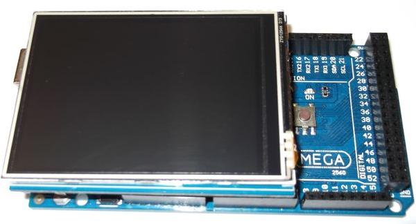
First of all, I want to tell you that this blog is for a project on 16x2 LCD display. For that I thought, Instead uses a color display, then it would be awesome. When I search Arduino Uno for a color display, I found the range using the Arduino UNO. Due to the size of the library I do not recommend using it on ATmega328 and ATmega32U4 as they only have 32KB of flash memory.
Finally for making this project bought Arduino Mega 2560. I'm very excited to try it as soon as possible and would like to convey that supports 240x320 resolution with a 2.4 "TFT display both the SD card and touch screen.
A small error is found and here is one of the amendments. I also abbreviations TFT changed to match them with.
1. Display
LEDA -> 5V
VCC -> 5V
RD -> 3.3V
GND -> GND
DB0->DB7 to pin D37->D30
DB8->DB15 to pin D22->D29
RS -> D38
WR -> D39
CS (pin15) -> D40
RSET-> D41
2. Touch Screen
Default pin number in example code:
T_CLK->D6
T_CS (pin30) ->D5
T_DIN ->D4
T_DO->D3
T_IRQ ->D2
3. SD Card:
SD_CLK -> D52
SD_DO -> D50
SD_DIN-> D51
SD_CS -> D53
Libraries and code:
We need UFTF library before running the example. Create the library and copy to Arduino/libraries. The examples can be found after restarting Arduino software.
Go to File > Examples > UTFT > Arduino (AVR) > UTFT_Demo_320x240
The only thing we have to do is just change the display model and the pins following the instruction. My TFT display model is ILI9325D_8 and the beginning of the code is as follow:
#include
// Declare which fonts we will be using extern uint8_t SmallFont[];
// Set the pins to the correct ones for your development shield


