Tuesday, December 1, 2015

Accelerometer witn an Arduino Motion Capture

The aim of this post was to introduce you how to create a gesture controlled robot using Arduino.
This can be breaks down into two key phases:
First one: Formation of a gesture control unit proficient of send wireless communications to a mobile rover stage. The development of this control unit will be discussed in this post.
Second one: Formation of a mobile rover stage proficient of receiving wireless commands from a gesture control unit. The following points are to explain a brief description of the requirements for the gesture control unit:
  1. The Arduino powered unit must be able of detect motion.
  2. The unit must be correlating the motion to a set of determined motions.
  3. The unit should be capable to provide visual feedback and instructions to the users via an LCD display.
  4. The unit must be able to transmit the signal via wireless communications.

Necessary Requirements:

1. Arduino Kit:

This kit includes:
4. XBee Shield for Arduino
6. XBee 1mW Wire Antenna - Series 1 (802.15.4)
7. 9V Battery Holder with Switch
8.Tools
  • Soldering Iron
  • Solder
  • Disoldering braid
  • Screwdriver

Assembly and Connections:

The first step towards construction of the control unit is to make the shields. This can be done by simply soldering all of the necessary pins into the board. Robomart.com provides superb instructions on how to properly build these shields. These guides also provide nice wiring guides and test code. However, I will go into the wiring and code in depth here as well.

With the shields and sensor properly assembled, the shields can be wired together with the Arduino UNO. The next one step will show the wiring for the ADXL 335.

Wiring for the ADXL 335:

The connection between the ADXL 335 and the Arduino can be able using 6 wires. The first connections are simply the 5V power and ground connections. The next three connections are for the output data from the 3 terminal of the accelerometer. 
Each of these outputs needs its own analog input pin. I choose pins A0, A1, and A2 for the X, Y, and Z outputs, respectively. The last connection needed is the 3V connection. This pin requires to be wired to the AREF pin on the Arduino board. This connection provides the sensor a baseline noise level for the Arduino. The readings will be quite useless without it.

LCD Display Connections:

The shield, not stacked, requires only 5V, ground, and 2 analog pins. The LCD requires the use of the I2C pins on the Arduino, found on A4 and A5. Looking at the shield, moving from the Reset button to the left, bottom row of pins, the 1st pin requires to be connected to A5 and the 2nd pin requires to be connected to pin A4. The ground pin is the 8th pin from the right and the 5V pin is the 10th pin from the right. The connections can be seen below.

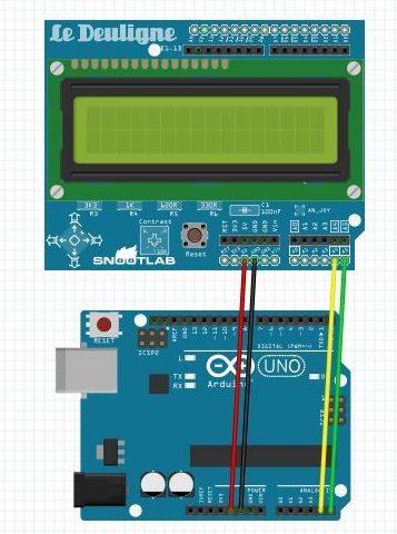
Connections of the XBee:

The connecting of the XBee is quite simple. Simply, place the XBee unit into the suitable slots on the shield. Now, place the shield on the Arduino, again. Finally, reconnect the wires for the accelerometer and the LCD into the same place they were on the Arduino.

Coding:

The code used to employ the control unit will be discussed below. This section will break down the code as it pertains to the different key sections of the code.
Namely, the sections to be discussed are:
  1. Libraries and global variables
  2. Routine setup
  3. Button detection
  4. LCD/motion detection routine

1. Libraries and Global Variables

This section will discuss the libraries and global variables needed to implement the motion detection routine.
#include
#include <Robomart_MCP23017.h>
#include
The Wire.h library comes with the Arduino IDE and does not need to be implemented. This library allows the Arduino to access the analog inputs needed to read the accelerometer. The other two libraries are there to provide the functions needed to use the Robomart RGB LCD.
Next one, we will discuss the global variables and objects declared to implement the code.
Robomart_RGBLCDShield LCD = Robomart_RGBLCDShield (); //define the LCD object as LCD
#define GREEN 0x2 //define the color green for the LCD
The above creates an object called LCD. This object will be used to call specific functions concerning the LCD device. In addition, the definition of GREEN in this case is a hex number used to tell the LCD what color to display the next in. This can be changed by using different hex numbers.
//Declare input pins
const int xInput = A0; const int yInput = A1; const int zInput = A2; int idleX = 0;
The above declares the analog input pins for the accelerometer.
int idleY = 0; int idleZ = 0; int idlemaxX = 0; int idlemaxY = 0;
int idlemaxZ = 0; int idleminX = 0; int idleminY = 0; int idleminZ = 0;
The above initializes the idle variables for the accelerometer. These must be defined as global variables because they are used in both the setup and loop routines. Later, one will see that the idle state is redefined each time the controller is turned on. This prevents errors should the environment conditions change the idle state values.
// Take multiple samples to reduce noise
const int sampleSize = 10;
int dir = 0;
Sample size is declared to reduce noise in the accelerometer measurements. Each time the values are read, 10 samples are taken and then averaged. The variable dir is used to communicate what button on the LCD has been pressed. This tells us the LCD what information to display.

2. Set-up Routine

In this section, we will discuss the setup routine used in the control unit.
analogReference(EXTERNAL);
The first step in this set-up routine is set the analogue reference voltage. This step helps to give a baseline for the amount of noise in the sensor readings. The analogue pins wouldn't read any change in reading, without it.
The LCD needs to be set up and a welcome message displayed.

lcd.begin(16, 2);
lcd.print("Welcome to the ");
lcd.setCursor(0,1);
lcd.print("HCRP");
lcd.setBacklight(GREEN);
delay(3000);
The set-up routine enters into the calibration phase of the code. Here, the idle state of the controlled is initialized. The inactive state is defined as laying flat. This is needed because motion is defined by deviations from the inactive state. The default state is inactive.
lcd.clear();
lcd.setCursor(0,0); lcd.print("Calibrating ");
lcd.setCursor(0,1); lcd.print("Lay flat");
delay(5000);
idleX = ReadAxis(xInput); idleY = ReadAxis(yInput); idleZ = ReadAxis(zInput);
idlemaxX = idleX+15; idlemaxY = idleY+15; idlemaxZ = idleZ+15;
idleminX = idleX-15; idleminY = idleY-15; idleminZ = idleZ-15;
lcd.clear();
lcd.setCursor(0,0); lcd.print("All done! ");
lcd.setCursor(0,1); lcd.print("Begin Control");
delay(3000);
In order to detect motion, the accelerometer values will have to exceed the maximum or minimum value for the idle state. Finally, the code tells the user that the calibration is finished and control of the rover is about to begin.

3. Button Detection

This Section describes the different actions to be taken by Arduino given different button presses on the LCD.
if (buttons)
{
lcd.clear();
lcd.setCursor(0,0);
if (buttons & BUTTON_UP)
  {
 lcd.print("Move "); dir = 0;
 }
if (buttons & BUTTON_DOWN)
{
lcd.print("Z accel "); lcd.setCursor(0, 1);
lcd.print(zRaw); dir = 1;
}
if (buttons & BUTTON_LEFT) {
lcd.print("Y accel "); lcd.setCursor(0, 1);
lcd.print(yRaw); dir = 2;
}
if (buttons & BUTTON_RIGHT) {
lcd.print("X accel "); lcd.setCursor(0, 1);
lcd.print(xRaw); dir = 3;
}
When the UP button on the LCD is pressed, then the Movement detected by the control unit is printed to the screen. This is the default display of the LCD. The variable dir global variable used to define the button that was pressed. It is used later in a switch/case statement to determine what information to continuously display. When the DOWN button is pressed, the raw Z acceleration data is shown. If the RIGHT button is pressed, the raw X acceleration data is shown. And if the LEFT button is pressed, the raw Y acceleration is displayed.

4. Motion Detection

This section describes how the controller decides what kind of motion is happening. Through testing, is determined that, as referenced from the idle state, this is the pattern that the motion of the controller follows. 
(G=greater, L=less, S=same)
Ideal: 510, 497, 627
Right 611, 492, 521.....G,S,L
Left 408, 496, 530.....L,S,L
Forward 512, 598, 526.....S,G,L
Reverse 514, 395, 536.....S,L,L
What this is saying is that, for an example, in order for there to be motion to the right, the X reading must be greater than inactive, the Y reading must be about the same, and the Z reading needs to be less than inactive. The same kind of logic follows for the other kinds of motion.
In the following code, the switch/case statement uses simple logic to determine the motion.
case 0:
lcd.clear();
lcd.setCursor(0,0);
lcd.print("Move");
lcd.setCursor(0, 1);
if (xRaw > idleX && yRaw > idleminY && yRaw < idlemaxY && zRaw < idleZ)
{
lcd.print("Right");
}
else if (xRaw < idleX && yRaw > idleminY && yRaw < idlemaxY && zRaw < idleZ)
{
lcd.print("Left");
}
else if (xRaw > idleminX && xRaw < idlemaxX && yRaw > idleY && zRaw < idleZ)
{
lcd.print("Forward");
}
else if (xRaw > idleminX && xRaw < idlemaxX && yRaw < idleY && zRaw < idleZ)
{
lcd.print("Reverse");
}
else {
lcd.print("Idle");
}

Covering Up and Future Scope:

In conclusion, it provided some information to set up the blog and to explore the different types of motion using an accelerometer that is my hope. In this blog, for the installation process and various sensors such as accelerometers and LCD displays and discussions were using.
Finally, the blog of accelerometer measurements to map the proposal provided access to write code you've gone through.
In addition, a follow-up on the blog to move around in the environment of the device is able to use motion to discuss how to build a rover will be written to. 
Thank you so much for pay attention for this post. If you have any bug or comment or any update feel free to post here.

Monday, November 30, 2015

Model of Arduino UNO Controlled Traffic Lights

For this project, first of all, I bought the Arduino UNO from www.robomart.com. Only a few days ago , and I am completely new to this , and was bored , so I think I would try a programming my hand and wanted a set of traffic lights. So I wrote this blog.

Required Components:

  • Arduino UNO
  • Bread board.
  • Jumpers (4 or 6)
  • 200ohm resistors (4 or 6)
  • 2 green LED's
  • 1 Red
  • 2 Yellow

Implemented Hardware:

So making the hardware necessary for this is very easy. Follow the following points:
  1. Take your bread board
  2. Put the red LED on the far left with Cathode in the negative rail of the board
  3. Skip 3 rows
  4. Put Yellow led in with cathode in negative rail
  5. Skip 3 rows
  6. Put green led in with cathode in negative rail
  7. Skip 3 rows
  8. Put the other green in with cathode in negative rail
  9. Skip 3 rows
  10. Put the final yellow led in with cathode in negative rail

Assembling:

Now, connect the jumpers.
Put one from each of the resistors and one from the negative rail to the Arduino UNO.
Negative rail = GND pin on Arduino UNO
Red LED = pin 12
1st yellow LED = pin 10
1st green LED = pin 8
2nd green LED = pin 6
2nd yellow LED = pin 5
Once, it’s done. It should look like this.

Final Results:

Now, for the programming (how can we programmed an Arduino), see my old posts. These will be definitely helping you. If any you have faced any problem at the time of coding, please post your question here. All done and it should be working, just upload it to your Arduino, and your set!
Feel free to post your suggestions, bugs & comment here.

Saturday, November 28, 2015

Glass with Accelerometer Controlled Light

I light the facility with a bed side of the glass as the project started. I have moved forward when I explored different uses in different contexts.

The glass case of bed:

Users need to wake up and drink water, he / she turns the glass. On glass flips, it is positioned at the bottom of the glass to the light thanks to the accelerometer. After lighting LEDs, in the glass in the dark from a pitcher to pour water becomes easier for the user. The glass is turned upside down when it is closed. In this case also protects the glass from dust and dirt.
For this scenario, a coloured light would be better. At the red light works well.

Other Scenarios:

It also houses two restaurants and a dinner during the time both tea light and the glass can be used as is. If it is used depends on the usage scenarios, Neo Pixels uses, desired color by using the USB port and the open source Arduino coding system (optimized) can be.

And also, can be fun at parties!

Materials and Tools:

  1. Materials:
  • 1 Toyo Sasaki HS Stackable glass
  • 1 Adafruit 5 V Pro Trinket
  • 1 Adafruit Neo pixel ring
  • A lithium -ion polymer battery - 3.7V 500mAh
  • 1 Adafruit Pro Trinket Li Ion / Li Poly battery bag
  • 1 Adafruit MMA8451 accelerometer
  • A slide switch
  • 1/8 " clear acrylic
  • Transparent filament for 3D printing
  • Glue

2. Tools:

  • Maker Bolt Replica-tor 2
  • Soldering iron
  • Wire

Coding:

Before soldering the components together when I first breadboard Arduino UNO suggest you to try the code. If everything works correctly, you can switch to Adafruit Pro Trinket.

Soldering the Component:

Solder the components together as seen on the circuit diagram. Make sure that you keep wires long enough to give a little bit flexibility to your circuit so that you can embed it into your enclosure with ease.


3D Printing and Laser Cutting:

  1. For a better light diffusion should use transparent filament.
  2. Printed on standard resolution. Make sure that you have the support material.
  3. Laser Clear acrylic 1/8 " thickness of 2.3 " diameter circle cut.

Assembling of A Component:

  1. 3D printed embeds components in the enclosure. It can be a bit tricky.
  2. Everything that fits properly to ensure its place.
  3. Control switches and USB outputs. They work well; you can glue the enclosure from the top part acrylic.
  4. With the assembly of a part.


Final Enjoyment:

By using the Micro-USB output can be customized with infinite possibilities.

Have any suggestion or any query, please post here. And thanks a lot to pay attention for this post.
Have fun guys..!!!!

Thursday, November 26, 2015

LED Web Server with use of Ethernet

Hello every one, In this post I’ll show how simple is to control things over the Internet using a few things like an Arduino Board, an Ethernet Shield and some LEDs to show the results. The Arduino will emulate a Web Server and after receives some command will turn on or off the LED.
 Connections

The LED library was removed for more compatibility.

What we goanna need?


How can perform the Connections?

Arduino board Ethernet Shield plug (look amazing how they fit). Arduino LED connects to pin. I pin, the use of 7, 6, 5 and 4. You can add 2 buttons on pins 8 and 9. RJ45 cable from your router to connect to the Ethernet Shield.

How to configure your router?


My router is a WRT54G from linksys, a wireless router with 4 LAN ports. The only thing you have to do to gain access through internet is Port forward the port you use on your server. In my case I use the port 8246 and a free local IP. Take attention please avoid use the port 80 or 8080, sometimes these ports are blocked.

Programming…?

With some modifications based on the Arduino sketch webserver.pde example. Easy to download a copy of my sketch is posted above.
I have a web page with more information to the load is to use a few tricks. HTML code for other things we have enough RAM, the program is stored in memory, so. Just ask any questions about the code.

Here's the code:

#include <Ethernet.h>
#include <SPI.h>
#include <avr/pgmspace.h>
prog_char string_0[] PROGMEM = "<html><body><h2>Controle de LED pela Internet</h2><font size= 4><form method=GET>";
prog_char string_1[] PROGMEM = "<br><input type=submit name=b1 value=Led1>";
prog_char string_2[] PROGMEM = "<br><input type=submit name=b2 value=Led2>";
prog_char string_3[] PROGMEM = "<br><input type=submit name=b3 value=Led3>";
prog_char string_4[] PROGMEM = "<br><input type=submit name=b4 value=Led4>";
prog_char string_5[] PROGMEM = "";  //"<br>Insert your name here:";
prog_char string_6[] PROGMEM = "";  //"<input name=msg value=no_name MAXLENGTH=20>";
prog_char string_7[] PROGMEM = "</form></body></html>";
prog_char string_8[] PROGMEM = "Ligada (ON)";
prog_char string_9[] PROGMEM = "Desligada (OFF)";
prog_char string_10[] PROGMEM = "<meta http-equiv=refresh content=30 > "; //for auto refresh
PROGMEM const char *string_table[] =     // change "string_table" name to suit
{  
  string_0,
  string_1,
  string_2,
  string_3,
  string_4,
  string_5,
  string_6,
  string_7,
  string_8,
  string_9,
  string_10
};
char buffer[85];    // make sure this is large enough for the largest string it must hold
byte mac[] = { 0xDE, 0xAD, 0xBE, 0xEF, 0xFE, 0xED };
byte ip[] = { 192, 168, 1, 134 };
byte gateway[] = { 192, 168, 1, 1 };
byte subnet[] = { 255, 255, 255, 0 };
String inString = String(35);
EthernetServer server(8246);
boolean led1 = false;
boolean led2 = false;
boolean led3 = false;
boolean led4 = false;
String msg="";
int tam=0;
int st1=9,st2=9,st3=9,st4=9;
void setup()
{
  Serial.begin(9600);
  Ethernet.begin(mac, ip,gateway,subnet);
  server.begin();
  Serial.println("Serial READY");
  Serial.println("Ethernet READY");
  Serial.println("Server READY");
  pinMode(4,OUTPUT);
  pinMode(5,OUTPUT);
  pinMode(6,OUTPUT);
  pinMode(7,OUTPUT);
  pinMode(8,INPUT);
  pinMode(9,INPUT);
}
void loop()
{
  EthernetClient client = server.available();
  int led=0;
  if (client) {
    // an http request ends with a blank line
    boolean current_line_is_blank = true;
    while (client.connected())
    {
      if (client.available())
     {
        char c = client.read();
        // if we've gotten to the end of the line (received a newline
        // character) and the line is blank, the http request has ended,
        // so we can send a reply
        if (inString.length() < 35) {
            inString.concat(c);
        }
         if (c == '\n' && current_line_is_blank) {
         if(inString.indexOf("b1")>0){
         if(led1==false){
         st1=8;
         led1=true;
         digitalWrite(4,HIGH);
        }
           else
             {
               st1=9;
               led1=false;
               digitalWrite(4,LOW);
             }
             led=1;
          }
           if(inString.indexOf("b2")>0){
           if(led2==false){
           st2=8;
           led2=true;
           digitalWrite(5,HIGH);
          }
             else
              {
               st2=9;
               led2=false;
               digitalWrite(5,LOW);
             }
             led=2;
            }
           if(inString.indexOf("b3")>0){
           if(led3==false){
           st3=8;
           led3=true;
           digitalWrite(6,HIGH);
          }
             else
               {
                st3=9;
                led3=false;
                digitalWrite(6,LOW);
             }
                led=3;
            }
               if(inString.indexOf("b4")>0){
               if(led4==false){
               st4=8;
               led4=true;
               digitalWrite(7,HIGH);
             }
             else
              {
               st4=9;
               led4=false;
               digitalWrite(7,LOW);
             }
             led=4;
            }
           /*
           if(inString.indexOf("msg")>0){
           char charBuf1[50];
           char charBuf2[50];
              strcpy(msg,(char*)inString.substring(inString.indexOf("g")+2,inString.indexOf(" H")));                        
              //Serial.print("msg: ");
              Serial.println(msg);
           }
         */
          // send a standard http response header
          client.println("HTTP/1.1 200 OK");
          client.println("Content-Type: text/html");
          client.println();
          strcpy_P(buffer, (char*)pgm_read_word(&(string_table[0]))); // Necessary casts and dereferencing, just copy.
          client.println( buffer );
          for (int i = 1; i < 8; i++)
          {
            strcpy_P(buffer, (char*)pgm_read_word(&(string_table[i]))); // Necessary casts and dereferencing, just copy.
            client.println( buffer );
            switch(i)
           {
            case 1: strcpy_P(buffer, (char*)pgm_read_word(&(string_table[st1]))); client.println( buffer ); break;
              case 2: strcpy_P(buffer, (char*)pgm_read_word(&(string_table[st2]))); client.println( buffer ); break;
              case 3: strcpy_P(buffer, (char*)pgm_read_word(&(string_table[st3]))); client.println( buffer ); break;
              case 4: strcpy_P(buffer, (char*)pgm_read_word(&(string_table[st4]))); client.println( buffer ); break;
           }
            delay(30);
          }
            if(digitalRead(8)==HIGH){
            client.println("<br>Botao 1, ON");
          }
           else
            {
            client.println("<br>Botao 1, OFF");
          }
            if(digitalRead(9)==HIGH){
            client.println("<br>Botao 2, ON");
          }
           else
            {
            client.println("<br>Botao 2, OFF");
          }
         
         //strcpy_P(buffer, (char*)pgm_read_word(&(string_table[10]))); client.println( buffer );
          break;
        }
         if (c == '\n') {
          // we're starting a new line
          current_line_is_blank = true;
        } 
         else if (c != '\r')
          {
          // we've gotten a character on the current line
          current_line_is_blank = false;
        }
      }
    }
    // give the web browser time to receive the data
    delay(1);
    inString = "";
    client.stop();
  }
}

Results:

We get everything so right that we start playing with our small web server can lead. 
Just type in your browser Arduino IP and port and will start to load the Web page. Load your sketch to your Arduino and do not forget to turn it on.
As you can see, with this method it is possible to control anything. With some modification on the program to realize the world is possible.
Any comments, bugs or suggestions, feel free to post here.

Wednesday, November 25, 2015

XY MIDI Pad with Arduino and TFT

I start micro controllers with new projects / experiments to some ideas / module / shield is seen after some time ago, my old project “2.4 Inch TFT LCD Control By Arduino Atmega " that would fit in perfectly found something interesting.
If you are interested in it, then link on my profile can search. I do not want to insist too much on this. It's a project I'm working on at the time and says undergone many transformations. I will not ever finish it, but I think working on / posted here will be some of whom have learned many interesting things discovered.

I'm excited with the idea of the visual feedback the XY controller (PAD) to make the TFT touch screen display was to use.

Shield’s Overview:

  • Resolution: 240x320. 
  • Size: 2.8 Inch. 
  • Colours: 262K 
  • TFT driver: ILI9325DS (supported by UTFT library) 
  • Touch driver: XPT2046 

Interface:

  1. TFT: 8bit data and 4bit control. 
  2. Touch Screen: 5 bit. 
  3. SD: 4bit. 

TFT Hardware Setup:

Installation is straightforward. You still need to select the correct voltage before use is. SD socket next to it, is a switch in the top right. 5V for Arduino Uno Arduino Mega and must choose. It is also not completely push shield.

Library Setup:

  1. First you need to install UTFT library. I'm going to do. You never know what might happen in the future. 
  2. Same thing about UTouch library. 

Touch Screen Calibration:

To work properly, the touch screen calibration is needed. UTouch revised calibrations to the library we need to run this sketch. We UTouch UTFT library with the library needs to match the orientation.

myGLCD.InitLCD(LANDSCAPE);
myTouch.InitTouch(LANDSCAPE);
These are 4 phases. In which we need to edit line #define selector for every phase and upload and run sketch step by step:
#define selector 1
In this phase we will verify that simple calibration put the correct resolution. This is an optional step. I put it here because the solution was designed by the author.
#define selector 2
It is the most important of the four. Here is the calibration. After uploading you like to sketch the picture top left point and the right - to get to the point; and amend.
void UTouch::InitTouch(byte orientation)
{
orient = orientation;
_default_orientation = 0;
touch_x_left = 306; //enter number for left most touch
touch_x_right = 3966; //enter number for right most touch
touch_y_bottom = 3906; //enter number for bottom most touch
touch_y_top = 174; //enter number for top most touch
disp_x_size = 320; // do not forget them if different
disp_y_size = 240; // do not forget them if different
prec = 10;
// ..................................................
We have to get to the screen touch_y_bottom values ​​and values ​​in relation to touch_y_top swapped looking. (TFT touch screens the origins of axes are different from the original). You will find out that the TFT for each model. You y -axis or x- axis values ​​of the TFT model dependent or may not need to swap. This particular model of the above works.
#define selector 3
Test program. Display XY coordinates of the touch point.
#define selector 4
Test program. Put a white pixel on the touch point. It is still very comfortable. If you see that you need to swap axis values ​​for x or y axis is mirrored on those pixels.

Example:

Everything is fine with calibration, so we have to move forward and UTFT and UTouch libraries can run the examples.
This is a direct reflection shoot camera appear usable pictures of the TFT was quite difficult to take note. I tried to photograph a mirror surface, so it seems like.

XY MIDI Pad:

You've seen the last instance they run quite slowly run. There is nothing wrong with TFT display and it is nothing wrong with the code or libraries. We 16MHz (or 20MHz) try to use an 8-bit microcontroller is it? We can send data than can run very fast indeed the performance.
Indeed we can improve the code and libraries, but the changes will not be dramatic. Ideally we etc. The more powerful processor, 32- bit (even 16- bit), DMA controller, > 150 MHz, (for the video buffer) and need more RAM...
Instead we need to speed up only a small area of the screen to update our programs can design.
I here XY Pad MIDI Arduino project put the whole code. I applied what I said above can be studied in detail to see how. However, I will comment on some sections.
Festival draw_Pad (long x, long y) in, before drawing new line, old lines clear them with the background color redrawing.
void draw_Pad(long x, long y)<br>{
// we draw 3 three lines for x and three lines for y
// for better visibility
myGLCD.setColor(pad_bk);
myGLCD.drawLine(old_x-1,pad_topY,old_x-1,pad_bottomY); // clear old line x-1
myGLCD.drawLine(old_x+1,pad_topY,old_x+1,pad_bottomY); // clear old line x+1
myGLCD.drawLine(old_x,pad_topY,old_x,pad_bottomY); // clear old line x
myGLCD.drawLine(pad_topX,old_y-1,pad_bottomY,old_y-1); // clear old line y-1 
myGLCD.drawLine(pad_topX,old_y+1,pad_bottomY,old_y+1); // clear old line y+1 
myGLCD.drawLine(pad_topX,old_y,pad_bottomY,old_y); // clear old line y
myGLCD.setColor(reticle_color);
myGLCD.drawLine(x-1,pad_topY,x-1,pad_bottomY); // draw new line x-1
myGLCD.drawLine(x+1,pad_topY,x+1,pad_bottomY); // draw new line x+1
myGLCD.drawLine(x,pad_topY,x,pad_bottomY); // draw new line x
myGLCD.drawLine(pad_topX,y-1,pad_bottomX,y-1); // draw new line1 y-1
myGLCD.drawLine(pad_topX,y+1,pad_bottomX,y+1); // draw new line2 y+1
myGLCD.drawLine(pad_topX,y,pad_bottomX,y); // draw new line3 y
}
I have not used the well known Arduino MIDI library (like my previous project). Instead I use a simple function to send MIDI CC commands: void SendMIDIControl(byte channel, byte controller, byte value) {
byte tmpChannel = (channel & 0b00001111)-1; //0= channel1...1=channel2... etc
tmpChannel = 0b10110000 + tmpChannel; //midi data first bit allways 1,
//+ 011 control change command
//+ midi channel
byte tmpController = controller & 0b01111111; //midi data first bit allways 0
byte tmpValue = value & 0b01111111; //midi data first bit allways 0
Serial1.write(tmpChannel);
Serial1.write(tmpController);
Serial1.write(tmpValue);
}

Important.!

We can not use the first serial port pins because its pins already used by TFT Shield. 
  • For Arduino UNO, we must use Software Serial. 
  • For Arduino MEGA, we can use Software Serial or Serial1/ Serial2. 
My Arduino USB MIDI Interface module can be replaced (theoretical) with a combination of MIDI Shield and USB to MIDI converter. I have not tested this way. 

Final Result:

I played for a while with this project after I noticed that there is room for improvement.
We have some physical push button with the right button can manage the settings. The pad will increase the utility. This project is a starting point for your MIDI projects (proof of concept) was designed to be as follows.
Y to X, in this case we need to make a separate map coordinates.
byte CoordToMIDI(unsigned int coord)
{
  float temp;
  temp=coord;
  temp=temp/1.72;
  return (byte)temp;  
}
will change in
byte CoordXToMIDI(unsigned int coord){
  float temp;
  temp=coord;
  temp=temp/another_value1; // depend of your virtual pad x size
  return (byte)temp;  
}
byte CoordYToMIDI(unsigned int coord){
  float temp;
  temp=coord;
  temp=temp/another_value2; // depend of your virtual pad y size
  return (byte)temp;  
}

We can also try to use the Arduino. Using this board 3V, because my interface need 3V level converter and switch TFT situation has moved on.
Huge thank to pay attention for this post.

Friday, November 20, 2015

2.4 Inch TFT LCD Control By Arduino Atmega8

First of all, I want to tell you that this blog is for a project on 16x2 LCD display. For that I thought, Instead uses a color display, then it would be awesome. When I search Arduino Uno for a color display, I found the range using the Arduino UNO. Due to the size of the library I do not recommend using it on ATmega328 and ATmega32U4 as they only have 32KB of flash memory.
All range of can be found with this link: https://www.robomart.com .


Arduino Atmega

Finally for making this project bought Arduino Mega 2560. I'm very excited to try it as soon as possible and would like to convey that supports 240x320 resolution with a 2.4 "TFT display both the SD card and touch screen.


Requirements:

1. Arduino MEGA 2560
2. 2.4" TFT Display
3. Wires
3. Small Breadboard 


2.4 TFT LCD

Connections:


A small error is found and here is one of the amendments. I also abbreviations TFT changed to match them with.

1. Display

LEDA -> 5V
VCC -> 5V
RD -> 3.3V 
GND -> GND
DB0->DB7 to pin D37->D30
DB8->DB15 to pin D22->D29
RS -> D38
WR -> D39
CS (pin15) -> D40
RSET-> D41

2. Touch Screen

Default pin number in example code:

T_CLK->D6
T_CS (pin30) ->D5
T_DIN ->D4
T_DO->D3
T_IRQ ->D2

3. SD Card:

SD_CLK -> D52
SD_DO -> D50
SD_DIN-> D51
SD_CS -> D53

Libraries and code:

We need UFTF library before running the example. Create the library and copy to Arduino/libraries. The examples can be found after restarting Arduino software.
Go to File > Examples > UTFT > Arduino (AVR) > UTFT_Demo_320x240
The only thing we have to do is just change the display model and the pins following the instruction. My TFT display model is ILI9325D_8 and the beginning of the code is as follow:

#include
// Declare which fonts we will be using extern uint8_t SmallFont[];
// Set the pins to the correct ones for your development shield
// ------------------------------------------------------------
// Arduino Uno / 2009:
// -------------------
// Standard Arduino Uno/2009 shield : ,A5,A4,A3,A2
// DisplayModule Arduino Uno TFT shield : ,A5,A4,A3,A2
/
/ Arduino Mega:
// -------------------
// Standard Arduino Mega/Due shield : ,38,39,40,41
// CTE TFT LCD/SD Shield for Arduino Mega : ,38,39,40,41
/
/ Remember to change the model parameter to suit your display module! UTFT myGLCD(ILI9325D_8,38,39,40,41);

Let's upload the code and see what happens...........

Result:

Next time I will try to do something a little bit complicated. Thanks for reading this it.